
PHOTOVOLTAIC MODULE
Contents
●Purpose of this guide
General
Safety precaution for installing a solar photovoltaic system
●Product Identification
●Mechanical Installation
Selecting the location
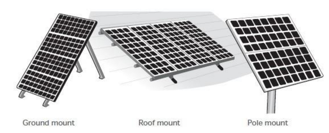
Selecting the proper support frame
Ground mount
Roof mount
Pole mount
General Installation
●Electrical Installation
Grid-connected electrical system
Grounding
General installation
●Commission and Maintenance
Blocking diodes and bypass diodes
Testing, commissioning and troubleshooting
Maintenance
Testing and replacing bypass diodes
●Disclaimer of Liability
Purpose of this guide
This guide contains information regarding the installation and safe handling of OVIERA SOLAR photovoltaic module (hereafter is referred to as "module "). QJ SOLAR hereafter is referred to as "QJ".
All instructions should be read and understood before attempting to install. If there are any question, please contact our sales department for further explanation. The installer should conform to all the safety precautions listed in this guide when installing the module. Local codes should also be followed in such installations.
Before installing a solar photovoltaic system,the installer should become familiar with the mechanical and electrical requirement for such a system. Keep this guide in a safe place for future reference (care and maintenance) and in case of sale or disposal of the module at the end of its useful life.
General
●Installing solar photovoltaic systems may require specialized skills and knowledge. Installation should be performed only by qualified person.
●The installer should assume the risk or all injury that might occur during installation, including without limitation, the risk of electric shock.
●One individual module may generate DC voltages greater than 30 volts when exposed to direct sunlight. Contact with a DC voltage of 30V or more is potentially hazardous.
●When disconnecting wires connected to a photovoltaic module that is exposed to sunlight, and electric arc may result. Such arcs may cause burns, may start fires and may otherwise create problems. Therefore, be extremely careful!
●Photovoltaic solar modules change light energy to direct-current electrical energy. They are designed for outdoor use. Modules may be ground mounted, mounted on rooftops, vehicles or boats. Proper design of support structures is the responsibility of the system designer and installer. Proper use of mounting holes is suggested in a following paragraph.
●Do not attempt to disassemble the module, and do not remove any attached nameplates or components.

●Do not apply paint or adhesive to module top surface.
●Artificially concentrated sunlight shall not be directed on the module or panel.

●When installing the system, abide with all local, regional and national statutory regulations. Obtain a building permit where necessary. Abide with any local and national regulations when mounting on vehicles or boats.
Safety precaution for installing a solar photovoltaic system
●Solar modules produce electrical energy when light shines on their front surface. The DC voltage may exceed 30V. If modules are connected in series, the total voltage is equal to the sum of the individual module voltages. If modules are connected in parallel, the total current is equal to the sum of individual module currents.
●Keep children well away from the system while transporting and installing mechanical and electrical components.
●Completely cover the module with an opaque material during installation to keep electricity from being generated.
●Do not wear metallic rings, watchbands, ear, nose, lip rings or other metallic devices while installing or troubleshooting photovoltaic systems.
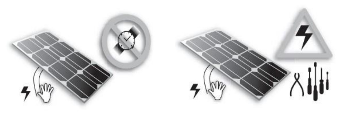
●Use only insulated tools that are approved for working on electrical installations.
●Abide with the safety regulations for all other components used in the system, including wiring and cables, connectors, charging regulators, inverters, storage batteries and rechargeable batteries, etc.
●Use only equipment, connectors, wiring and support frames suitable for use in a solar electric systems. Always use the same type of module within a particular photovoltaic system.
●The electrical characteristics are within ±3% of the indicated values of Pmax under standard test conditions (irradiance of 100mW/cm2, AM 1.5 spectrums, and a cell temperature of 25℃ {77ºF} )
●Under normal conditions, a photovoltaic module is likely to experience conditions that produce more current and/or voltage than reported at standard test conditions. Accordingly, the values of ISC and VOC marked on this module should be multiplied by a factor of 1,25 when determining component voltage ratings, conductor current ratings, fuse sizes, and size of controls connected to the PV output."
●Refer to Section 690-8 of the National Electrical Code for an additional multiplying factor of 125 percent (80 percent derating) which may be applicable.
Product identification
Each module has three labels on its rear and front sides providing the following information:
●Nameplate: describes the product type; rated power, rated current, rated voltage, open circuit voltage, short circuit current, all as measured under standard test conditions; dimension etc., the maximum system voltage for TUV listed modules is 1000 volts DC and is shown on the nameplate.
●Barcode: each individual module has a unique serial number. There are two barcodes on module. One is permanently attached to the interior of the module visible when viewing from the front of the module. This barcode is inserted at the beginning of laminating.
●Do not remove any label. If the label is removed, the product warranty will no longer be honored by QJ.
Mechanical Installation
● Selecting the location
⊙Select a suitable location for installation of the module.
⊙The module should be facing true south in northern latitudes and true north in southern latitudes for best power production.
⊙For detailed information on the best elevation tilt angle for the installation, refer to standard solar photovoltaic installation guides or a reputable solar installer or systems integrator.
⊙The module should not be shaded at any time of the day.
⊙Do not use module near equipment or in locacollected.
●Selecting the proper support frame
⊙Always observe the instructions and safety precautions included with the support frame to be used with the module.
⊙No attempt must be made to drill holes in the glass surface of the module. To do so will void the warranty.
⊙Do not drill additional mounting holes in the frame of the module. Doing so will void the warranty.
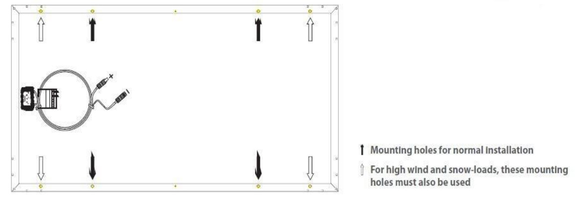
⊙Modules must be securely attached to the mounting structure using four mounting points for normal installation. If additional wind or snowloads are anticipated for this installation, additional mounting points are also used. Refer to the drawing, below, load calculations are left to the system designer or installer.
⊙The support module mounting structure must be made of durable, corrosion-resistant and UV-resistant material..
●Ground mount
⊙Select the height of the mounting system to prevent the lowest edge of the module from being covered by snow for a long time in winter in areas that experience heavy snowfalls. In addition, assure the lowest portion of the module is placed high enough so that it is not shaded by plants or trees or damaged by sand and stone driven by wind.
●Roofmount
⊙When installing a module on a roof or building, ensure that it is securely fastened and cannot fall as a result of wind or snow loads.
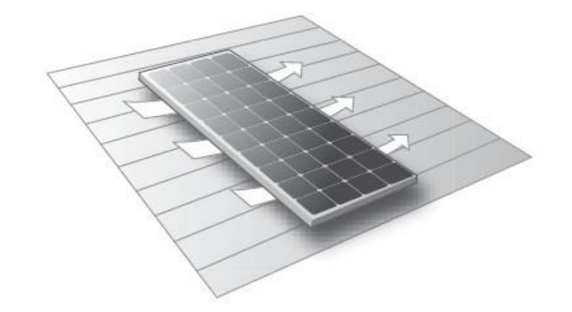
⊙Provide adequate ventilation under a module for cooling (5cm minimum air space between module and mounting surface).
⊙When installing module on a roof, ensure that the roof construction is suitable. In addition, any roof penetration required to mount the module must be properly sealed to prevent leaks.
⊙In some cases, a special support frame may be necessary.
⊙The roof installation of solar modules may affect the fireproofing of the house construction.
⊙The modules are rated fire Class C, and are suitable for mounting over a Class A roof.
⊙To maintain the corresponding fire prevention level, the tilt angle should be no less than 5 in/ft (127 mm/305 mm) when the modules are mounted on the roof.
⊙The National Electric Code required the use of a properly sized GFDI on photovoltaic arrays installed on dwellings. Refer to the NEC for further information on earth ground fault breakers.
For field connections, use minimum 12 AWG copper wires insulated for a minimum of 90 °C.
Recommended maximum series/parallel module configurations; ([1000V/(1.25*Voc)]/[fuse rating/Isc+1],如 QJP300-72,Voc is43.4V,Ifuse is15A,Isc is 9.27A, for 72 cells modules series ,Recommended maximum series/parallel module configuration :18/2.
⊙When installing the module on a roof or building, do so in calm winds. Installing a module during strong winds may cause accidents.
Mechanical Installation
●Pole mount
⊙When installing a module on a pole, choose a pole and module mounting structure that will withstand anticipated winds for the area.
●General installation
⊙Module mounting must use the pre-drilled mounting holes in the frame.
⊙The most common mounting is achieved by mounting the module using the four symmetry points close to the inner side on module frame.
⊙If excessive wind or snow loads are expected, all eight mounting holes must be used. ⊙Do not lift the module by grasping the module’s junction box or electrical leads. ⊙Do not stand or step on module.
⊙Do not drop module or allow objects to fall on module.
⊙To avoid glass breakage, do not place any heavy objects on the module.
⊙Do not set the module down hard on any surface.
⊙Inappropriate transport and installation may break the glass of the module.
Electrical Installation
●Grid-connected electrical system
⊙The DC electrical energy generated by photovoltaic systems may also be converted to AC and connected to a utility grid system. As local utilities’ policies on connecting renewable energy systems to their grids vary from region to region, consult a qualified system designer or integrator to design such a system. Permits are normally required to install such a system and the utility must formally approve and inspect such a system before it can be connected to the grid.
●Grounding
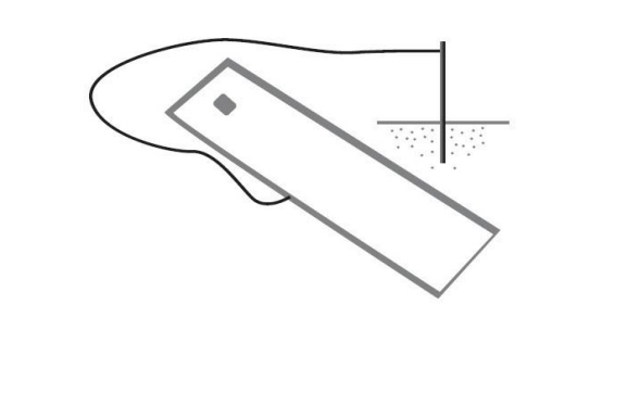
⊙The module frame must be properly grounded (refer to NEC clause 250). The grounding wire must be properly fastened to the module frame to assure good electrical contact. Use the recommended type, or an equivalent, connector for this wire.
⊙If the support frame is made of metal, the surface of the frame must be electroplated and have excellent conductivity.
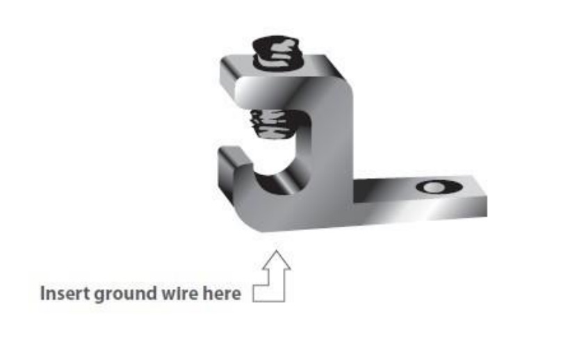
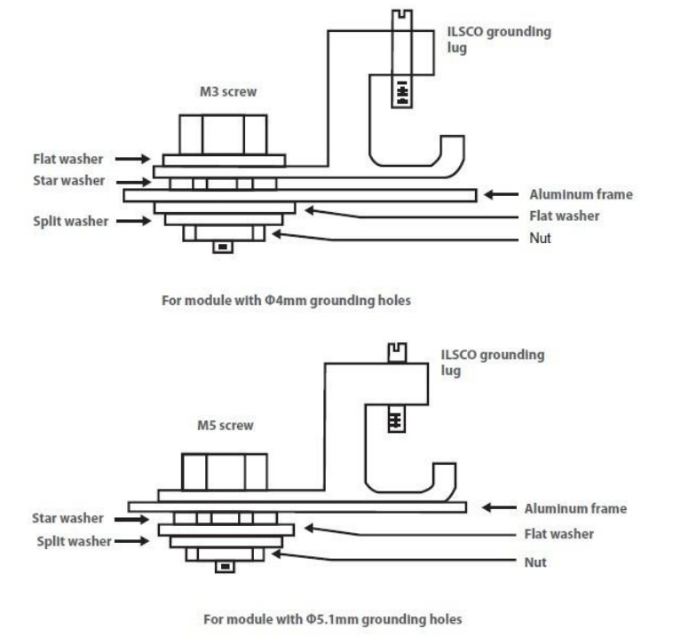
⊙We recommend the lay-in lug (Cat.No.GBL4-DBT;company:ILSCO) when grounding. First strip 16mm insulating jacket from the end of the ground wire (4- 14STR) carefully to avoid nicking or cutting conductors, insert the wire into the slot of the lug (see the picture), and screw down the slotted screw.
Electrical Installation
Next assemble the recommended ILSCO grounding lug to the aluminum frame using stainless steel M3 or M5 screw and hardware as shown below. Note: there are two different size grounding holes, the smaller of which is being phased out. Further, buildup of hardware for mounting the grounding lug are the same---except for the M3 screw, and added flat washer is mounted directly under the M3 screw head. The star waher is fitted directly under the grouding lug and makes electrical contact by penetrating the anodized coating of the aluminum frame. The screw assembly is further fitted with a flat washer, then a split lock washer and finally a nut to secure the entire assembly, as shown. Recommended torque of M3 or M5 screw assembly is 0.8NM or 1.5NM.
Electrical Installation
●General installation
⊙Do not use module of different configurations in the same system.
⊙Several modules are connected in series and then in parallel to form a PV array, especially for application with a high operation voltage. If modules are connected in series, the total voltage is equal to the sum of individual voltages.
⊙For applications requiring high currents, several photovoltaic modules can be connected in parallel; the total current is equal to the sum of individual currents.
⊙Module is supplied with Multicontact connectors(PV-KBT4 and PV-KST4) to use for system electrical connections. Use the National Electric Code to determine system wiring size (refer to NEC clause 310), type and temperature rating of conductors to be connected to the module’s connectors. Wiring connected to the module’s wiring should be #12AWG (minimum) and must be temperature rated at 90℃ (minimum).
⊙In Canada installation shall be in accordance with CSA C22. 1, Safety Standard for Electrical Installations, Canadian Electrical Code, Part1.
⊙The cross section area of cable and the capacity of connector must be selected to suit the maximum system short circuit current, otherwise the cable and connector will be
overheated under large current. Refer to NEC for details.
⊙Module overcurrent protection, rated for DC use.
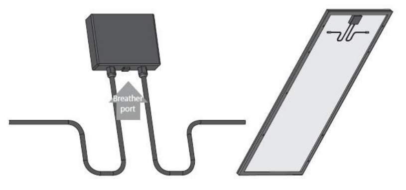
⊙The junction box is fitted with a breather port. The breather port must be mounted facing down and can not be exposed to rain. Therefore, the junction box must be on the higher side of the module when it is mounted.
Commission and Maintenance
QJ recommends that all work in commissioning and maintenance of a system must be performed by a qualified solar PV technician.
●Blocking diodes and bypass diode
⊙Blocking diodes prevent current flowing from the battery to the module when no electricity is being generated. It is recommended to use blocking diodes when a charging regulator is not used. Your specialist dealer can advise you with regards to suitable types, such as Schottky diodes.
⊙In systems with more than two modules in series, high reverse current can flow through cells that are shaded partially or outright when part of a module is shaded and the rest is exposed to the sun. These currents can cause the affected cells to get very hot and could even damage the module. To protect module from such high reverse currents, by-pass diodes are used in module. All modules rated greater then 55 watt have bypass diode already integrated in the junction box. In the unlikely event of diode failure, OVIERA recommends a qualified service technician be employed to determine if diodes have failed and to make replacement.
⊙Protect yourself against electricity shocks while commissioning and maintaining the solar power system.
●Testing, commissioning and troubleshooting
Test all electrical and electronic components of your system before commissioning it. Follow the instructions in the guides supplied with the components and equipment.
⊙Testing modules connected in series before they are connected to system. To determine Voc and Isc in the following tests, the module(s) must be exposed to the sun and not connected to a load. Observe personal safety when making these measurements.
⊙Check the open-circuit voltage (Voc) of every series module using a digital multimeter (Fluke 170 series are recommended). The measured system Voc should correspond to the sum of the Vocs of the individual module. You will find the rated voltage in the technical specifications of the type of the module used and in the tables at the end of this installation guide. If the measured value is significantly lower than the expected value, proceed as described under “Troubleshooting an excessively low voltage” .
⊙Determine the short-circuit current (Isc) of every series circuit. It can be measured directly by connecting the digital multimeter connected in the two terminals of series circuit or module. Attention, the rated scale of the ammeter or the rated current of load should more than 1.25 times than the rated short-circuit current of series module. You will find the rated current in the technical specifications of the type of module used. The measured value can vary significantly, depending on weather conditions, the time of day and shading of the module.
⊙Troubleshooting low voltages
To identify the commonly low voltage and excessively low voltage, the commonly how voltage mentioned here is the decrease of open-circuit voltage of the module, which is caused by the temperature rising of solar cells or lower irradiance. Excessively low voltage is typically caused by improper connections at the terminals or defective bypass diodes.
Commission and Maintenance
⊙First check all wiring connections to make sure it is not open-circuit or is not connection well.
⊙Check the open-circuit voltage of each module.
⊙Fully cover the modules with an opaque material.
⊙Disconnect the wiring at both terminals of the modules.
⊙Remove the opaque material from the module to be checked and measure the open-circuit
voltage at its terminals.
⊙If the measured voltage is only half of the rated, this indicates a defective bypass diode. Refer to “Testing and replacing bypass diodes” .
⊙In the case of not very low irradiance, if the voltage across the terminals differs from the rated value by more than 5 percent, this indicates a bad electrical connection.
●Maintenance
QJ recommends the following maintenance in order to ensure optimum performance of the module.
⊙Clean the glass surface of the module as necessary. Always use water and a soft sponge or cloth for cleaning. A mid, non-abrasive cleaning agent can be used to remove stubbom dirt.
⊙Check the electrical and mechanical connections every six months to verify that they are clean, secure and undamaged.
⊙If any problem arises, have them investigated by a competent specialize. Observe the maintenance instructions for all components used in the system, such as support frames, charging regulators, inverters, batteries, etc.
●Testing and replacing bypass diodes
Removing the bypass diodes should be done only by a competent PV technician and after the module has been disconnected from the system.
⊙Place module face down on a soft, flat surface insert a 3mm flat screwdriver into the slot on the junction box cover. (The cover has a sign of screwdriver). Gently pull up the four slots until the cover been opened.
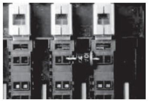
⊙Insert the 3mm flat screwdriver into a hole alongside of diode and near one mounting hole of the diode, pry the screwdriver in the opposite direction of diode and gently pull the diode up until the lead comes free. Do the same in the other mounting hole of the diode, and repeat until the diode is free.
Commission and Maintenance
●Note the orientations of the polarity markings on the diodes.
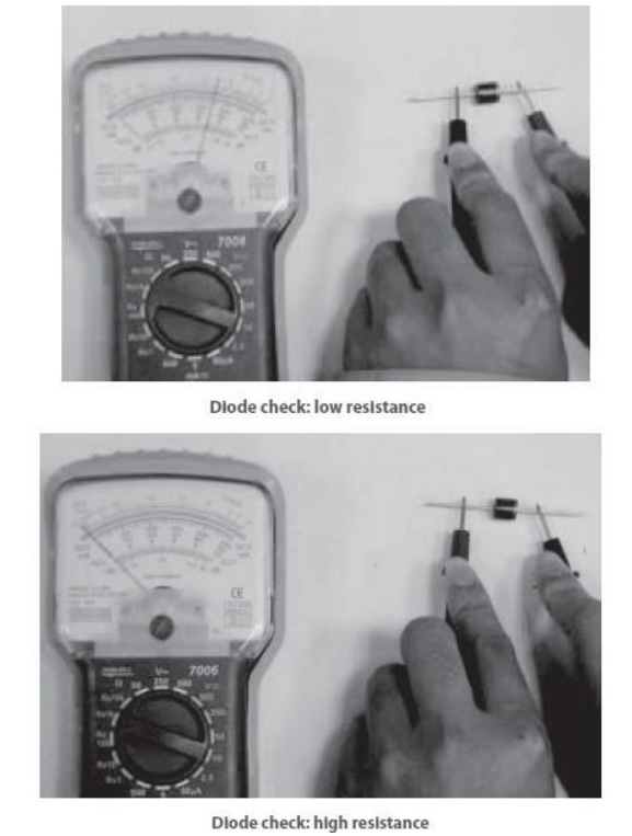
●Check the resistance of the diodes by using the digital multimeter’s ohms scale. Resistance should be low in one direction, then when leads are reversed on the diode’s terminals the resistance should be high, as illustrated in the two pictures below. If a diode has a low resistance in both directions, it is probably shorted. If it has high resistance in both directions it is probably open. In either case it should be replaced.
●Replace a defective diode with a diode of the same type, and ensure that its polarity making is oriented the same way as the original diode.
●Finally, check the open-circuit voltage (Voc) of the module, as described previously, and replace both covers.
Disclaimer of liability
●Because the use of this manual and the conditions or methods of installation, operation, use and maintenance of photovoltaic (PV) product are beyond QJ’s control, QJ does not accept responsibility and expressly disclaims liability for loss, damage, or expense arising out of or in any way connected with such installation, operation , use or maintenance.
●No responsibility is assumed by QJ for any infringement of patens or other rights of third parties, which may result from use of the PV product. No license is granted by implication or otherwise under any patent or patent rights.
●The information in this manual is based on QJ knowledge and experience and is believed to the reliable; but such information including product specification (without limitations) and suggestions do not constitute a warranty, expresses or implied. QJ reserve the right to change the manual, the PV produce, the specifications, or product information sheets without prior notice.
Electrical Characteristics
Please refer to QJ Catalogue.
products catalogue
Maximum System Voltage: 1000VDC
Power Tolerance: ±3%
Application classes: Class A
Class A: General access, hazardous voltage, hazardous power applications Modules rated for use in this application class may be used in systems operating at greater than 50 V DC or 240 W, where general contact access is anticipated. Modules qualified for safety through this part of IEC 61730 and IEC 61730-2 and within this application class are
considered to meet the requirements for safety class II.
|
Model |
Module Dimensions |
Weight |
Isc |
Voc |
Imp |
Vmp |
Pmax |
Maxi mum series |
|
QJP335 |
1956x992x40(mm) |
20.3kg |
9.69A |
44.4V |
9.06A |
37V |
335W |
15A |
|
QJP330 |
1956x992x40(mm) |
20.3kg |
9.58A |
44.28V |
8.95A |
36.9V |
330W |
15A |
|
QJP325 |
1956x992x40(mm) |
20.3kg |
8.91A |
44. 16V |
8.32A |
36.8V |
325W |
15A |
|
QJP320 |
1956x992x40(mm) |
20.3kg |
9.33A |
44.04V |
8.72A |
36.7V |
320W |
15A |
|
QJP315 |
1956x992x40(mm) |
20.3kg |
9.22A |
43.92V |
8.61A |
36.6V |
315W |
15A |
|
QJP310 |
1956x992x40(mm) |
20.3kg |
9.11A |
43.8V |
8.5A |
36.5V |
310W |
15A |
|
QJP305 |
1956x992x40(mm) |
20.3kg |
8.97A |
43.68V |
8.38A |
36.4V |
305W |
15A |
|
QJP300 |
1956x992x40(mm) |
20.3kg |
8.85A |
43.56V |
8.27A |
36.3V |
300W |
15A |
|
QJP295 |
1956x992x40(mm) |
20.3kg |
8.72A |
43.44V |
8.15A |
36.2V |
295W |
15A |
|
QJP290 |
1956x992x40(mm) |
20.3kg |
8.61A |
43.32V |
8.04A |
36. 1V |
290W |
15A |
|
QJP285 |
1956x992x40(mm) |
20.3kg |
8.48A |
43.2V |
7.92A |
36.0V |
285W |
15A |
|
QJP280 |
1640x992x40(mm) |
18.2kg |
9.71A |
37.08V |
9.07A |
30.9V |
280W |
15A |
|
QJP275 |
1640x992x40(mm) |
18.2kg |
9.56A |
36.96V |
8.93A |
30.8V |
275W |
15A |
|
QJP270 |
1640x992x40(mm) |
18.3kg |
9.41A |
36.84V |
8.8A |
30.7V |
270W |
15A |
|
QJP265 |
1640x992x40(mm) |
18.3kg |
9.27A |
36.72V |
8.66A |
30.6V |
265W |
15A |
|
QJP260 |
1640x992x40(mm) |
18.3kg |
9.13A |
36.6V |
8.53A |
30.5V |
260W |
15A |
|
QJP255 |
1640x992x40(mm) |
18.3kg |
8.98A |
36.48V |
8.39A |
30.4V |
255W |
15A |
|
QJP250 |
1640x992x40(mm) |
18.3kg |
8.83A |
36.36V |
8.26A |
30.3 V |
250W |
15A |
|
QJP245 |
1640x992x40(mm) |
18.3kg |
8.68A |
36.24V |
8.12A |
30.2 V |
245W |
15A |
|
QJP240 |
1640x992x40(mm) |
18.3kg |
8.54A |
36. 12V |
7.98A |
30. 1 V |
240W |
15A |
|
QJP235 |
1640x992x40(mm) |
18.3kg |
8.39A |
36V |
7.84A |
30.0 V |
235W |
15A |
|
QJP230 |
1640x992x40(mm) |
18.3kg |
8.24A |
35.88V |
7.7A |
29.9 V |
230W |
15A |
|
QJP225 |
1640x992x40(mm) |
18.3kg |
8.08A |
35.76V |
7.56A |
29.8 V |
225W |
15A |
|
QJP220 |
1325*992*40(mm) |
14.5kg |
9.53A |
29.64V |
8.91 A |
24.7 V |
220W |
15A |
|
QJP215 |
1325*992*40(mm) |
14.5kg |
9.36A |
29.52V |
8.74 A |
24.6 V |
215W |
15A |
|
QJP210 |
1325*992*40(mm) |
14.5kg |
9. 18A |
29.4 V |
8.58 A |
24.5 V |
210W |
15A |
|
QJP205 |
1325*992*40(mm) |
14.5kg |
8.99A |
29.28V |
8.41 A |
24.4 V |
205W |
15A |
|
QJP200 |
1325*992*40(mm) |
14.5kg |
8.81A |
29. 16V |
8.23 A |
24.3 V |
200W |
15A |
|
QJP195 |
1325*992*40(mm) |
14.5kg |
8.62A |
29.04V |
8.06 A |
24.2 V |
195W |
15A |
|
QJP190 |
1325*992*40(mm) |
14.5kg |
8.44A |
28.92V |
7.89A |
24.1 V |
190W |
15A |
|
QJP165 |
1480*675*40(mm) |
11.5kg |
9.49A |
22.32V |
8.87A |
18.6 V |
165W |
15A |
|
QJP160 |
1480*675*40(mm) |
11.5kg |
9.26A |
22. 2V |
8.65A |
18.5 V |
160W |
15A |
|
QJP155 |
1480*675*40(mm) |
11.5kg |
9.02A |
22.08V |
8.43A |
18.4 V |
155W |
15A |
|
QJP150 |
1480*675*40(mm) |
11.5kg |
8.78A |
21.96V |
8.2A |
18.3 V |
150W |
15A |
|
QJP145 |
1480*675*40(mm) |
11.5kg |
8.53A |
21.84V |
7.97A |
18.2 V |
145W |
15A |
|
QJP140 |
1480*675*40(mm) |
11.5kg |
8.28A |
21.72V |
7.74A |
18.1 V |
140W |
15A |
|
QJP110 |
1008*675*40(mm) |
7.9kg |
9.49A |
14.88V |
8.87A |
12.4 V |
110W |
15A |
|
QJP105 |
1008*675*40(mm) |
7.9kg |
9. 14A |
14.76V |
8.54A |
12.3 V |
105W |
15A |
|
QJP100 |
1008*675*40(mm) |
7.9kg |
8.78A |
14.64V |
8.2A |
12.2 V |
100W |
15A |
|
QJP95 |
1008*675*40(mm) |
7.9kg |
8.41A |
14.52V |
7.86A |
12.1 V |
95W |
15A |
|
QJP90 |
850*675*40(mm) |
6.96kg |
9.36A |
12.36V |
8.74A |
10.3 V |
90W |
15A |
|
QJP85 |
850*675*40(mm) |
6.96kg |
8.92A |
12.24V |
8.34A |
10.2 V |
85W |
15A |
|
QJP80 |
850*675*40(mm) |
6.96kg |
8.48A |
12. 12V |
7.93A |
10.1 V |
80W |
15A |
|
QJP75 |
690*675*40(mm) |
5.86kg |
9.67A |
9.96V |
9.04A |
8.3 |
75W |
15A |
|
QJP70 |
690*675*40(mm) |
5.86kg |
9. 14A |
9.84V |
8.54A |
8.2 V |
70W |
15A |
|
QJP65 |
690*675*40(mm) |
5.86kg |
9.72A |
8.6V |
8.03A |
8.1 V |
65W |
15A |
|
QJP55 |
535*675*40(mm) |
4.72kg |
9.49A |
7.44V |
8.87A |
6.2 V |
55W |
15A |
|
QJP50 |
535*675*40(mm) |
4.72kg |
8.78A |
7.32V |
8.2A |
6.1 V |
50W |
15A |
|
QJP45 |
535*675*40(mm) |
4.72kg |
8.03A |
7.2V |
7.5A |
6.0 V |
45W |
15A |
|
QJP35 |
376*675*40(mm) |
3.66kg |
8.92A |
5.04V |
8.34A |
4.2 V |
35W |
15A |
|
QJP30 |
376*675*40(mm) |
3.66kg |
7.83A |
4.92V |
7.32A |
4.1 V |
30W |
15A |
|
QJP25 |
535*356*40(mm) |
2.91kg |
8.63A |
3.72V |
8.07A |
3.1 V |
25W |
15A |
|
QJP20 |
535*356*40(mm) |
2.91kg |
7. 14A |
3.6V |
6.67A |
3.0 V |
20W |
15A |
|
QJP10 |
220*356*40(mm) |
1.6kg |
10.3A |
1.25V |
9.62A |
1.04 V |
10W |
15A |
|
QJM355 |
1956*992*40(mm) |
20.2kg |
10.3A |
44.4V |
9.59A |
37V |
355W |
15A |
|
QJM350 |
1956*992*40(mm) |
20.2kg |
10.15 A |
44.28V |
9.49A |
36.9 V |
350W |
15A |
|
QJM345 |
1956*992*40(mm) |
20.2kg |
10.03 A |
44. 16V |
9.38A |
36.8 V |
345W |
15A |
|
QJM340 |
1956*992*40(mm) |
20.2kg |
9.92A |
44.04V |
9.27A |
36.7 V |
340W |
15A |
|
QJM335 |
1956*992*40(mm) |
20.2kg |
9.79A |
43.92V |
9. 16A |
36.6 V |
335W |
15A |
|
QJM330 |
1956*992*40(mm) |
20.2kg |
9.68A |
43.8V |
9.04A |
36.5 V |
330W |
15A |
|
QJM325 |
1956*992*40(mm) |
20.2kg |
9.56A |
43.68V |
8.93A |
36.4 V |
325W |
15A |
|
QJM320 |
1956*992*40(mm) |
20.2kg |
9.44A |
43.56V |
8.82A |
36.3 V |
320W |
15A |
|
QJM315 |
1956*992*40(mm) |
20.2kg |
9.32A |
43.44V |
8.71A |
36.2 V |
315W |
15A |
|
QJM310 |
1956*992*40(mm) |
20.2kg |
9. 19A |
43.32V |
8.59A |
36.1 V |
310W |
15A |
|
QJM305 |
1956*992*40(mm) |
20.2kg |
9.07A |
43. 2V |
8.48A |
36.0 V |
305W |
15A |
|
QJM295 |
1640*992*40(mm) |
18. 1kg |
10.22 |
37.08V |
9.55A |
30.9 |
295W |
15A |
|
QJM290 |
1640*992*40(mm) |
18. 1kg |
10.08 A |
36.96V |
9.42A |
30.8 V |
290W |
15A |
|
QJM285 |
1640*992*40(mm) |
18. 1kg |
9.93A |
36.84V |
9.28A |
30.7 V |
285W |
15A |
|
QJM280 |
1640*992*40(mm) |
18. 1kg |
9.79A |
36.72V |
9. 15A |
30.6 V |
280W |
15A |
|
QJM275 |
1640*992*40(mm) |
18. 1kg |
9.65A |
36.6V |
9.02A |
30.5 V |
275W |
15A |
|
QJM270 |
1640*992*40(mm) |
18. 1kg |
9.51A |
36.48V |
8.89A |
30.4 V |
270W |
15A |
|
QJM265 |
1640*992*40(mm) |
18. 1kg |
9.36A |
36.36V |
8.75A |
30.3 V |
265W |
15A |
|
QJM260 |
1640*992*40(mm) |
18. 1kg |
9.22A |
36.24V |
8.61A |
30.2 V |
260W |
15A |
|
QJM255 |
1640*992*40(mm) |
18. 1kg |
9.07A |
36. 12V |
8.48A |
30.1 V |
255W |
15A |
|
QJM250 |
1580x1066x50(mm) |
21kg |
5.81A |
57.8V |
5. 19A |
48.2 V |
250W |
10A |
|
QJM245 |
1580x1066x50(mm) |
21kg |
5.71A |
57.7V |
5. 10A |
48.1 V |
245W |
10A |
|
QJM240 |
1580x1066x50(mm) |
21kg |
5.61A |
57.6V |
5.01A |
48.0 V |
240W |
10A |
|
QJM235 |
1325*992*40(mm) |
14.4kg |
10.18 A |
29.64V |
9.52A |
24.7 V |
235W |
15A |
|
QJM230 |
1325*992*40(mm) |
14.4kg |
10.01 A |
29.52V |
9.35A |
24.6 V |
230W |
15A |
|
QJM225 |
1325*992*40(mm) |
14.4kg |
9.83A |
29.4V |
9. 19A |
24.5 V |
225W |
15A |
|
QJM220 |
1325*992*40(mm) |
14.4kg |
9.65A |
29.28V |
9.02A |
24.4 V |
220W |
15A |
|
QJM215 |
1325*992*40(mm) |
14.4kg |
9.47A |
29. 16V |
8.85A |
24.3 V |
215W |
15A |
|
QJM210 |
1325*992*40(mm) |
14.4kg |
9.29A |
29.04V |
8.68A |
24.2 V |
210W |
15A |
|
QJM205 |
1325*992*40(mm) |
14.4kg |
9.11A |
28.92V |
8.51A |
24.1 V |
205W |
15A |
|
QJM200 |
1325*992*40(mm) |
14.4kg |
8.92A |
28.8V |
8.34A |
24 V |
200W |
15A |
|
QJM195 |
1580x808x50 (mm) |
15.5kg |
6.01A |
43.6V |
5.37A |
36.4 V |
195W |
10A |
|
QJM190 |
1580x808x50 (mm) |
15.5kg |
5.86A |
43.5V |
5.23A |
36.3 V |
190W |
10A |
|
QJM185 |
1580x808x50 |
15.5kg |
5.72A |
43.4V |
5. 11A |
36.2 |
185W |
10A |
|
QJM180 |
1580x808x50 (mm) |
15.5kg |
5.59A |
43.3V |
4.99A |
36.1 V |
180W |
10A |
|
QJM175 |
1480*675*40(mm) |
11.4kg |
10.13 A |
22.2V |
9.46A |
18.5 V |
175W |
15A |
|
QJM170 |
1480*675*40(mm) |
11.4kg |
9.89A |
22.08V |
9.24A |
18.4 V |
170W |
15A |
|
QJM165 |
1480*675*40(mm) |
11.4kg |
9.65A |
21.96V |
9.02A |
18.3 V |
165W |
15A |
|
QJM160 |
1480*675*40(mm) |
11.4kg |
9.41A |
21.84V |
8.8A |
18.2 V |
160W |
15A |
|
QJM155 |
1480*675*40(mm) |
11.4kg |
9. 17A |
21.72V |
8.57A |
18.1 V |
155W |
15A |
|
QJM130 |
1074x808x50 (mm)) |
11kg |
5.96A |
29.3V |
5.32A |
24.4 V |
130W |
10A |
|
QJM125 |
1074x808x50 (mm)) |
11kg |
5.79A |
29.0V |
5. 17A |
24.2 V |
125W |
10A |
|
QJM120 |
1074x808x50 (mm)) |
11kg |
5.60A |
28.8V |
5.01A |
24.0 V |
120W |
10A |
|
QJM115 |
1008*675*40(mm) |
7.8kg |
9.93A |
14.88V |
9.28A |
12.4 V |
115W |
15A |
|
QJM110 |
1008*675*40(mm) |
7.8kg |
9.58A |
14.76V |
8.95A |
12.3 V |
110W |
15A |
|
QJM105 |
1008*675*40(mm) |
7.8kg |
9.21A |
14.64V |
8.61A |
12.2 V |
105W |
15A |
|
QJM100 |
1008*675*40(mm) |
7.8kg |
8.85A |
14.52V |
8.27A |
12.1 V |
100W |
15A |
|
QJM95 |
850*675*40(mm) |
6.9kg |
9.87A |
12.36V |
9.23A |
10.3 V |
95W |
15A |
|
QJM90 |
850*675*40(mm) |
6.9kg |
9.45A |
12.24V |
8.83A |
10.2 V |
90W |
15A |
|
QJM85 |
850*675*40(mm) |
6.9kg |
9.01A |
12. 12V |
8.42A |
10.1 V |
85W |
15A |
|
QJM80 |
850*675*40(mm) |
6.9kg |
8.56A |
12V |
8A |
10 V |
80W |
15A |
|
QJM75 |
690*675*40(mm) |
5.8kg |
9.67A |
9.96V |
9.04A |
8.3 V |
75W |
15A |
|
QJM70 |
690*675*40(mm) |
5.8kg |
9. 14A |
9.84V |
8.54A |
8.2 V |
70W |
15A |
|
QJM65 |
690*675*40(mm) |
5.8kg |
8.59A |
9.72V |
8.03A |
8.1 V |
65W |
15A |
|
QJM55 |
535*675*40(mm) |
4.65kg |
9.49A |
7.44V |
8.87A |
6.2 V |
55W |
15A |
|
QJM50 |
535*675*40(mm) |
4.65kg |
8.78A |
7.32V |
8.2A |
6.1 |
50W |
15A |
|
QJM35 |
376*675*40(mm) |
3.6kg |
8.92A |
5.04V |
8.34A |
4.2 V |
35W |
15A |
|
QJM30 |
376*675*40(mm) |
3.6kg |
7.83A |
4.92V |
7.32A |
4.1 V |
30W |
15A |
|
QJM25 |
535*356*40(mm) |
2.85kg |
8.63A |
3.72V |
8.06A |
3.1 V |
25W |
15A |
|
QJM10 |
220*356*40(mm) |
1.55kg |
9.73A |
1.32V |
9.09A |
1.1 V |
10W |
15A |
|
QJM260-125 |
1580x1066x50(mm) |
21kg |
6.00A |
58.2V |
5.36A |
48.5 V |
260W |
10A |
|
QJM255-125 |
1580x1066x50(mm) |
21kg |
5.91A |
58.0V |
5.28A |
48.3 V |
255W |
10A |
|
QJM235-125 |
1580x1066x50(mm) |
21kg |
5.49A |
57.4V |
4.91A |
47.9 V |
235W |
10A |
|
QJM230-125 |
1580x1066x50(mm) |
21kg |
5.39A |
57.3V |
4.81A |
47.8 V |
230W |
10A |
|
QJM225-125 |
1580x1066x50(mm) |
21kg |
5.28A |
57.2V |
4.72A |
47.7 V |
225W |
10A |
|
QJM220-125 |
1580x1066x50(mm) |
21kg |
5. 17A |
57.0V |
4.63A |
47.5 V |
220W |
10A |
|
QJM175-125 |
1580x808x50 (mm) |
15.5kg |
5.45A |
43. 1V |
4.87A |
35.9 V |
175W |
10A |
|
QJM170-125 |
1580x808x50 (mm) |
15.5kg |
5.35A |
42.7V |
4.78A |
35.6 V |
170W |
10A |
|
QJM165-125 |
1580x808x50 (mm) |
15.5kg |
5.22A |
42.5V |
4.66A |
35.4 V |
165W |
10A |
|
QJM115-125 |
1074x808x50 (mm)) |
11kg |
5.41A |
28.8V |
4.83A |
23.8 V |
115W |
10A |
|
QJM110-125 |
1074x808x50 (mm) |
11kg |
5.24A |
28.2V |
4.68A |
23.5 V |
110W |
10A |
|
QJM95-125 |
1200x552x50 (mm) |
7.8kg |
5.94A |
21.5V |
5.31A |
17.9 V |
95W |
10A |
|
QJM90-125 |
1200x552x50 (mm) |
7.8kg |
5.72A |
21. 1V |
5. 11A |
17.6 V |
90W |
10A |
|
QJM85-125 |
1200x552x50 (mm) |
7.8kg |
5.48A |
20.9V |
4.89A |
17.4 V |
85W |
10A |
Mounting Using Clamps on Long Edge of Module
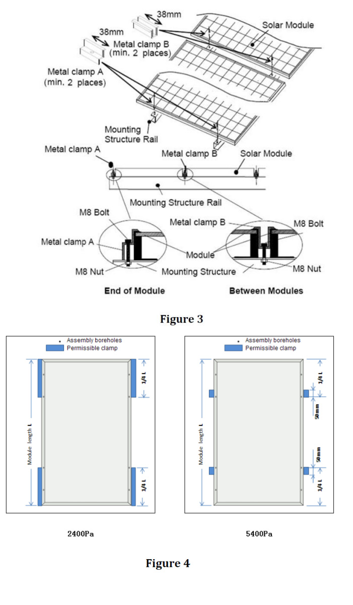
QJ modules recommend to be mounted using clamps designed for solar modules as shown in Figures 3.
A module should be attached on a mount or support structure rail by metal clamps. The metal clamp should fulfill the following specifications:
Size: not less than 1.5”(38mm)width
Thickness: not less than 0.12”(3mm)
Material: Aluminum alloy
Recommendation of bolt torque range: 16N.m to 25N.m.
It is always recommmendable to position the clamps at the location of the holes in the module’s frame.
Recommendation of clamps position range:Figure 4 for reference.
The Modules clamps must not contact the front glass or deform the frame in any way.Avoid shading effects from the Modules clamps.Drainage holes on the Modules frame must not be closed or obscured by the clamps.
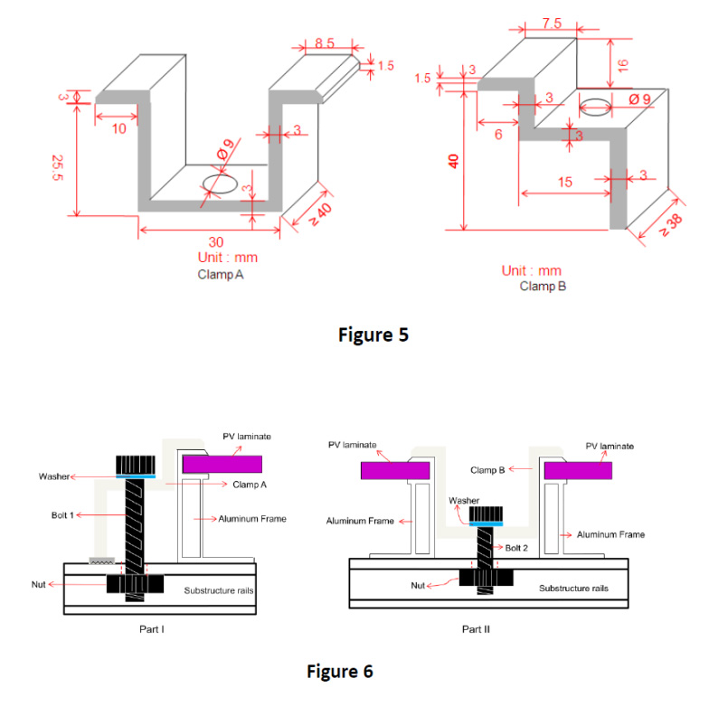
Figure 5 to Figure 14 is just used for the 60 cells modules and the dimension is 1640*992*40(mm)mm.
The details of Part 1and Part 11 in from Figure 6 to Figure 14 is reference to Figure 6
For Figure 7 and Figure8,the PV modules are designed for a maximum fo 2400Pa wind load.
For from Figure 9to Figure 14,the PV modules are designed for a maximium of 2400Pa Wind load and 5400Pa withstand heavy accumulations of snow and ice.